Seal & Cylinder Source Retrofit for Nasa’s F-1 Rocket Engine G4049 Vertical Telescopic Installation Cylinder
SCS, Inc. -Seal & Cylinder Source, Inc., One of the leading hydraulic & pneumatic suppliers located in Clinton Township, Michigan, has successfully completed a significant 3 month project to retrofit Nasa’s F-1 Rocket Engine G4049 Vertical Telescopic Installation Cylinder. This project is in preparation for an additional 16 more units due to come in the 4th quarter of 2015-16. The project culminates part of SCS, Inc’s extensive experience in remanufacturing and retrofitting re-purposed aerospace equipment with viable applications for commercial aerospace markets.
![]()
Seal & Cylinder Source, Inc. 44250 North Avenue
Clinton Township MI 48036
P: 877-905(SEAL) 7325 F: 586-791-9033
[email protected] www.sealandcylinder.com
Nasa’s F-1 Rocket Engine G4049 Vertical Telescopic Installation Cylinder in preparation for an additional 16 more units in 2015-16.

Inception: F-1 Rocket Engine G4049 Engine Vertical Installer
When the Saturn V S-IC (first) stages were manufactured at the Michoud Assembly Facility, their F-1 rocket engines were installed while the stages were in the horizontal position, using an engine horizontal installation tool and a facility hoist. However, whenever S-IC stages were shipped or delivered (other than from the VAB to the launch pad), the stages were transported without nozzle extensions installed on the F-1 engines; the nozzle extensions were installed while the stages were in the vertical position.
In 2012, the U.S. aerospace industry contributed $118.5 billion in export sales to the U.S. economy. The industry’s positive trade balance of $70.5 billion is the largest trade surplus of any manufacturing industry and came from exporting 64.3 percent of all aerospace production.
Looking ahead, 90% of those surveyed expected to increase or maintain current surplus parts purchasing. Of those that will decrease, the decline will be due to retirement of a specific aircraft type that’s using surplus parts to save costs. The surplus parts market is booming. In 2001, the air transport serviceable parts market was worth about $11 billion, with just 10%, or $1.1 billion, claimed by surplus parts, according to SH&E data. Today, surplus parts account for about 18% of a $15 billion market, and the share could climb to 20% by 2015. The biggest share of surplus parts, 65%, is in engines, largely because of the opportunity.
It can be a little intimidating to think about the pedigree of those on the NASA staff. They have expertise and experience going back decades that includes sending people and billions of dollars of high-tech equipment into space. The current engine MRO makes up about 40% of the global MRO market, nearly twice as much as the next-largest category. Components–which at 21% of the global MRO market rank second to engines in total spend–account for 30% of the surplus business. Airframe parts–typically motor-driven systems like flaps–round out the balance.
“There is a tremendous growth opportunity to supply products and services to the commercial aerospace industry. Even though some of the surplus equipment is considered obsolete and in some cases over 50 years in age. If the engineering is solid we are able to implement new technologies in order to re-purpose antiquated equipment. SCS, Inc. specializes in products and services to meet our customers unique requirements. It is our ability to custom manufacture and duplicate obsolete seals and components that keep or customers fleets in operation. ” Remarked Jarrett Dygas, President of Seal & Cylinder Source, Inc.
Components–which at 21% of the global MRO market rank second to engines in total spend–account for 30% of the surplus business. 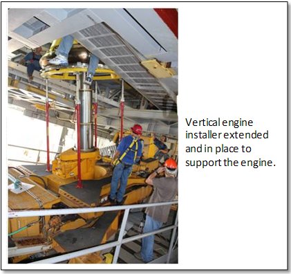 Airframe parts–typically motor-driven systems like flaps–round out the balance. Perhaps the biggest change on the surplus parts front is in sourcing. In 2007, half of the surplus parts came directly from the aerospace industry or brokers, while the other half were harvested directly from equipment in opporation. Now, the share of surplus parts being sourced directly from part-outs is about 82%.
Currently, commercial space companies are involved in activities such as launching and maintaining commercial and government satellites, supporting national security assets, and contracting with NASA’s Commercial Cargo and Commercial Crew programs in support of the International Space Station. Even more companies are testing and developing capabilities for the next generation of space exploration and discovery technologies. The SPACE Act facilitates a pro-growth environment for the developing commercial space industry by improving safety, encouraging private sector investment, and creating more stable and predictable regulatory conditions.
F1 Rocket Engine Telescopic Cylinder Repair
Seal & Cylinder Source, Inc. has payed special attention to detail is necessary to insure proper function when you are repairing aerospace type equipment. Unlike industrial hydraulic application, aerospace equipment requires exact specifications to be meet and certified before any unit can be approved for service in the field.
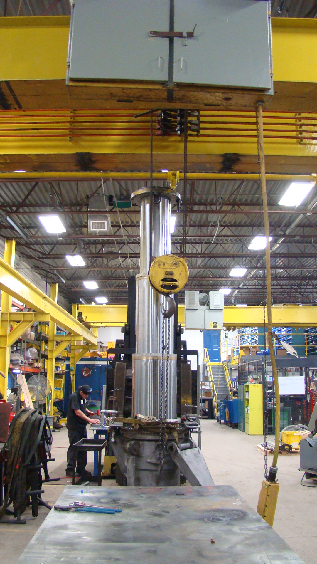
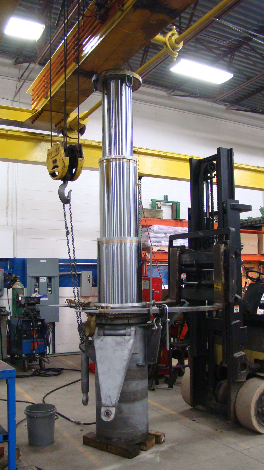
Completed Retrofit For Nasa’s F-1 Rocket Engine G4049 Vertical Telescopic Installation Cylinder
F1 Rocket Cylinder Specifications:
All Surfaces have been reworked to provide proper guiding and reduce the amount of seal friction. Per Nasa specification all the rods and tubes have been re-chromed to increase lifespan. Chrome is inherently porous so it stores lubricant, prolonging the life of seals. The extremely hard, The sealing material is the preferred option for hydraulic applications in aerospace flight controls and landing gear. It has operating temperatures from -196° to 260° C (-320° to 500° F) and is capable of withstanding pressures up to 35 MPa (5000 psi) for prolonged periods.
| Cylinder Bore 1: | 18.00” | Rod Diameter 1: | 17.996” | Stroke 1: | 20.00” |
| Cylinder Bore 2: | 15.502” | Rod Diameter 2: | 15.498” | Stroke 2: | 28.50” |
| Cylinder Bore 3: | 13.00” | Rod Diameter 3: | 12.996” | Stroke 3: | 31.50” |
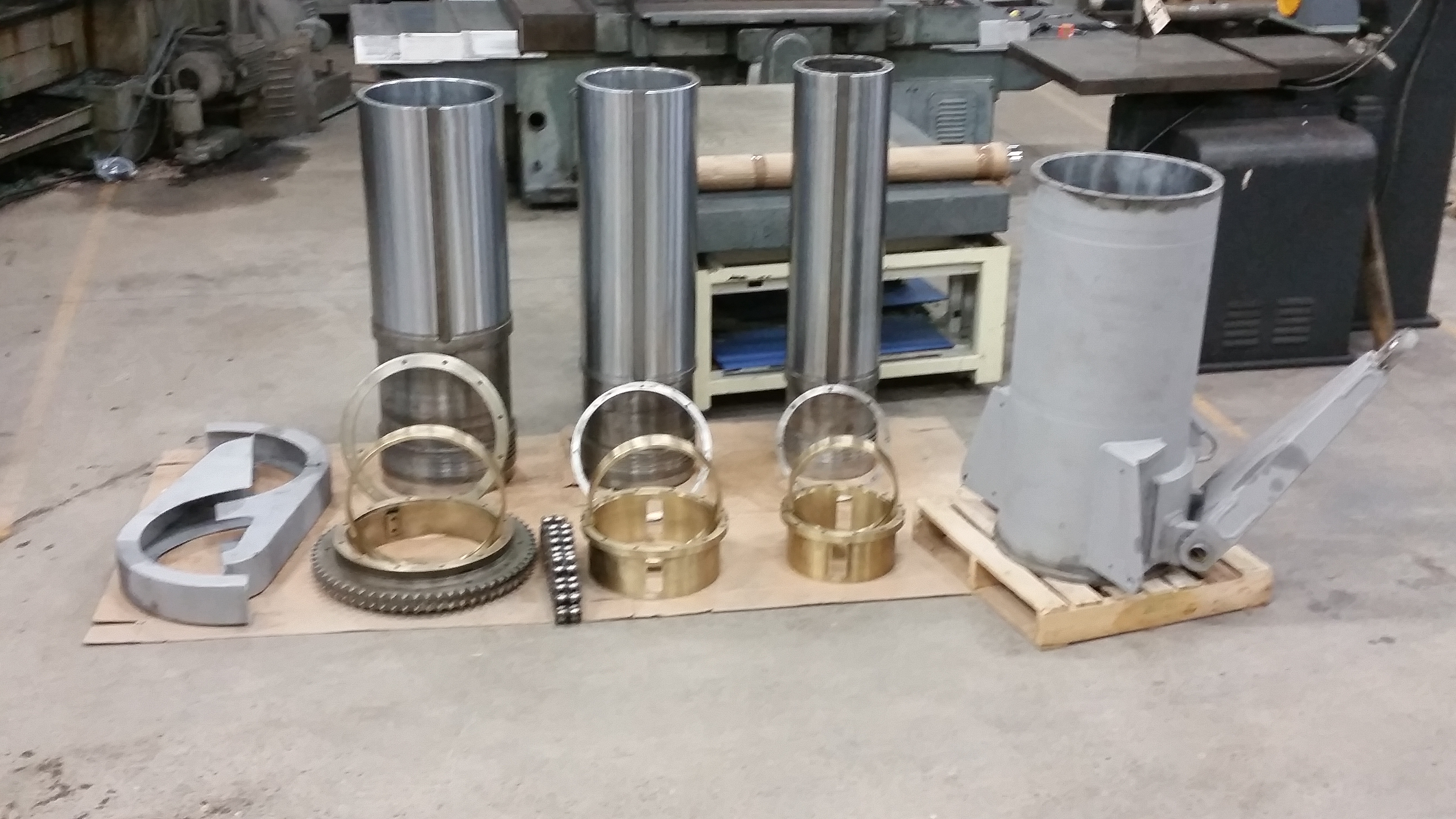
F1 Rocket Cylinder Components Before Installation
F1 Rocket Cylinder Test:
Standardized methods for pressure-fatigue testing of hydraulic components have been established by the National Fluid Power Association (NFPA), SAE International, and the International Organization for Standardization (ISO). These test procedures are designed to realistically replicate fatigue failure under accelerated test conditions in order to provide a cost-effective means of assessing component reliability.
Testing F1 Rocket Cylinder @ SCS, Inc.
“This accomplishment would not be possible without the extraordinary team work from all of our employees and astounding support from our supply partners. When I was child I was fascinated with the concept space exploration. I couldn’t be more pleased to have the opportunity to support NASA in its endeavors.” Explained Jarrett Dygas, President of Seal & Cylinder Source, Inc.
Pre and post ignition procedures
During static test firing, the kerosene-based RP-1 fuel left hydrocarbon deposits and vapors in the engine post test firing. These had to be removed from the engine to avoid problems during engine handling and future firing, and the solvent trichloroethylene (TCE) was used to clean the engine’s fuel system immediately before and after each test firing. The cleaning procedure involved pumping TCE through the engine’s fuel system and letting the solvent overflow for a period ranging from several seconds to 30–35 minutes, depending upon the engine and the severity of the deposits. For some engines, the engine’s gas generator and LOX dome were also flushed with TCE prior to test firing.
Specifications
| Apollo 4, 6, and 8 | Apollo 9–17 | |
|---|---|---|
| Thrust (sea level): | 1,500,000 lbf (6.7 MN) | 1,522,000 lbf (6.77 MN) |
| Burn time: | 150 seconds | 165 seconds |
| Specific impulse: | 260 seconds (2.5 km/s) | 263 seconds (2.58 km/s) |
| Chamber pressure: | 70 bar (1,015 psi; 7 MPa) | 70 bar (1,015 psi; 7 MPa) |
| Engine weight dry: | 18,416 lb (8,353 kg) | 18,500 lb (8,400 kg) |
| Engine weight burnout: | 20,096 lb (9,115 kg) | 20,180 lb (9,150 kg) |
| Height: | 19 ft (5.8 m) | |
| Diameter: | 12.3 ft (3.7 m) | |
| Exit to throat ratio: | 16 to 1 | |
| Propellants: | LOX & RP-1 | |
| Mixture mass ratio: | 2.27:1 oxidizer to fuel | |
| Contractor: | NAA/Rocketdyne | |
| Vehicle application: | Saturn V / S-IC 1st stage – 5-engines | |
F-1 improvements

F-1 on display at the
U.S. Space & Rocket Center
in Huntsville, Alabama.
F-1 thrust and efficiency were improved between Apollo 8 (SA-503) and Apollo 17 (SA-512), which was necessary to meet the increasing payload capacity demands of later Apollo missions. There were small performance variations between engines on a given mission, and variations in average thrust between missions. For Apollo 15, F-1 performance was:
- Thrust (average, per engine, sea level liftoff): 1,553,200 lbf (6.909 MN)
- Burn time: 159 seconds
- Specific impulse: 264.72 seconds (2.5960 km/s)
- Mixture ratio: 2.2674
- S-IC total sea level liftoff thrust: 7,766,000 lbf (34.54 MN)
Measuring and making comparisons of rocket engine thrust is more complicated than it first appears. Based on actual measurement the liftoff thrust of Apollo 15 was 7,823,000 lbf (34.80 MN), which equates to an average F-1 thrust of 1,565,000 lbf (6.96 MN) – significantly more than the specified value.
More Than Seal & Cylinders………Solutions!
THE HISTORY: F-1 Rocket Engine G4049 Engine Vertical Installer
When the Saturn V S-IC (first) stages were manufactured at the Michoud Assembly Facility, their F-1 rocket engines were installed while the stages were in the horizontal position, using an engine horizontal installation tool and a facility hoist. However, whenever S-IC stages were shipped or delivered (other than from the VAB to the launch pad), the stages were transported without nozzle extensions installed on the F-1 engines; the nozzle extensions were installed while the stages were in the vertical position.
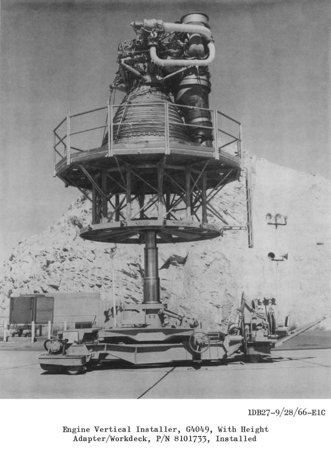
From time to time, it was also necessary to remove or install an F-1 engine on an S-IC which was in the vertical position. Although this was an unusual event for most stages, the S-IC-T stage (the static test stage, used to static test the S-IC stage and its five F-1 engines in Marshall Space Flight Center’s S-IC test stand) was delivered to the test stand without engines. Engines were installed while the S-IC-T stage was installed vertically in the test stand. Engines were also swapped out and moved from one position to another at various times throughout the static test program. The G4049 Engine Vertical Installer was used to install nozzle extensions and F-1 engines when an S-IC stage was in the vertical position.
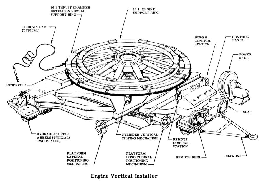
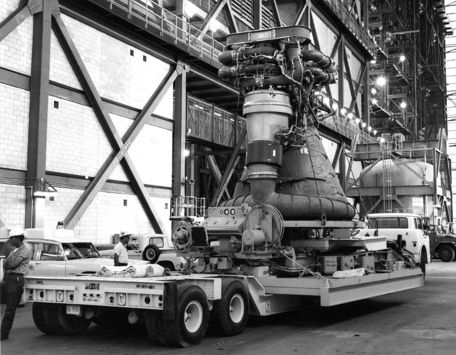
F-1 rocket engine G4049 engine vertical installer
Click image for a 2075×1461 pixel version of this image in a new window. Photo courtesy Vince Wheelock. Cleanup by heroicrelics.
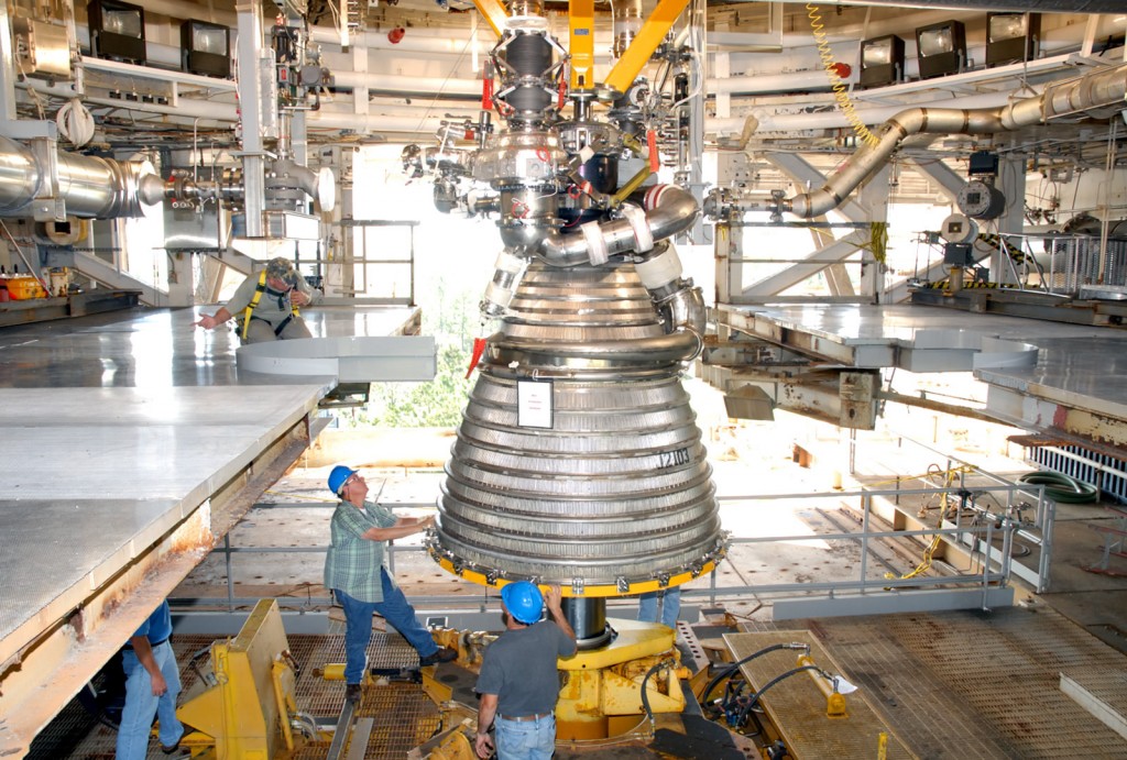
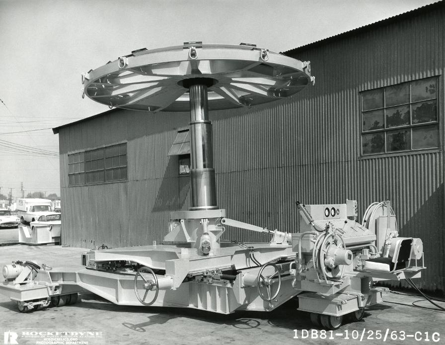
The F-1 engine was placed on the installer, which was used to position the engine vertically and horizontally and to raise the engine to the facility attach point.
F-1 rocket engine G4049 engine
Click image for a 1166×1110 pixel version of this image in a new window. From page 49 (p. 50 in the PDF) of the “Data Pages” of the Marshall Space Flight Center F-1 Engine Static Test Stand entry on the Historic American Building Survey/Historic American Engineering Record. Extraction from an advance review copy and cleanup by heroicrelics.
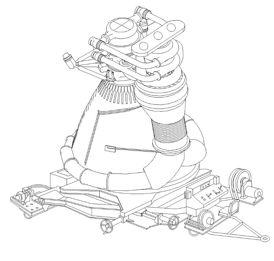
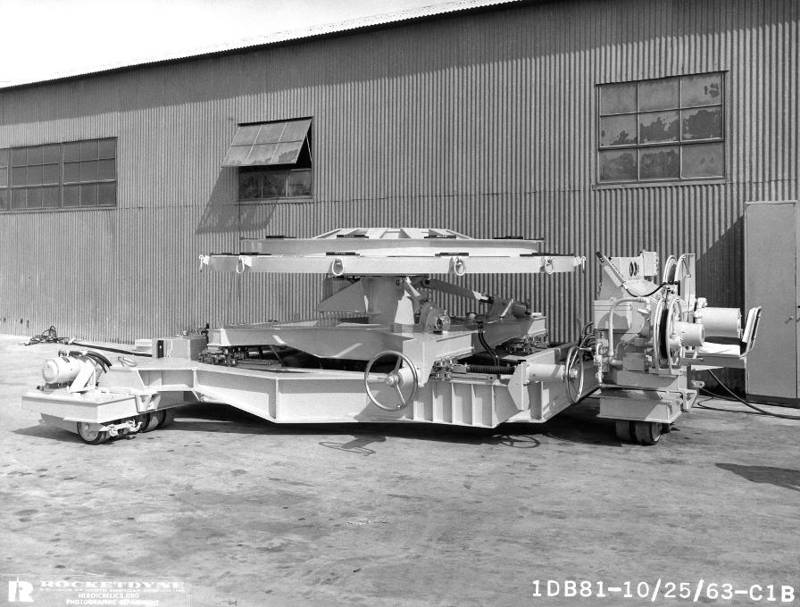
As described in various Saturn V ground support equipment-related documentation, the engine vertical installer was an electrohydraulic-operated, self-propelled, lifting and positioning unit for the engine. The vertical installer consisted of a dual-pressure hydraulic system, electrical system, control console, manually-operated tilting mechanism, manually-operated horizontal positioning mechanism, a hydraulically-operated azimuth drive, a pair of hydraulically-operated drive wheels and gearboxes, and a three-stage lifting cylinder, all supported on a triangular frame. Twelve wheels, including the hydraulic drive wheels, supported the vehicle frame. It also had an attachable tow bar. The vertical installer platform or cylinder could be operated manually with control valves on the control panel, or remotely using the remote-control station. The drive wheels could be operated from the control panel only.
Here is a series of photos showing the engine vertical installer being put through its paces:
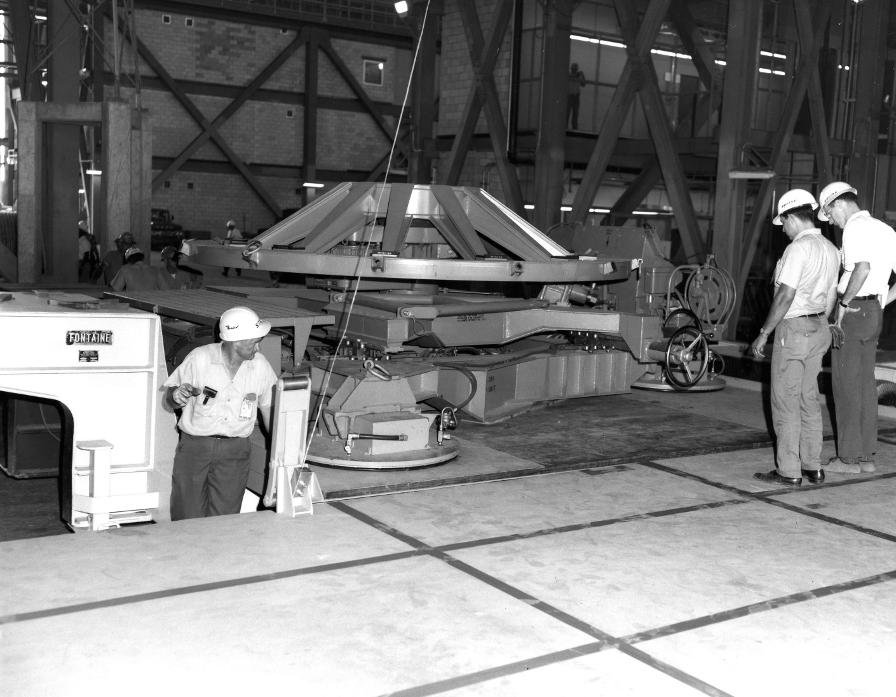
F-1 rocket engine G4049 engine vertical installer
Click image for a 2816×2136 pixel version of this image in a new window. Photo courtesy Vince Wheelock. Cleanup by heroicrelics.
F-1 rocket engine G4049 engine vertical installer
Click image for a 2805×2172 pixel version of this image in a new window. Photo courtesy Vince Wheelock. Cleanup by heroicrelics.
F-1 rocket engine G4049 engine vertical installer
Click image for a 3614×4893 pixel version of this image in a new window. From page A-44 of the Final Report, F-1 Engine Qualification Test Program, located in the Thompson collection of the archives of the University of Alabama at Huntsville. Scan and cleanup by heroicrelics.
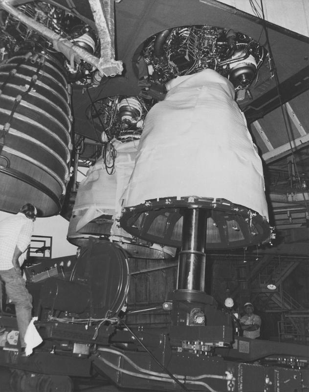
Here are three photos of the engine vertical installer being used to position F-1 engines for installation of the S-IC-T stage. The first photo is undated; while I don’t know whether it is of an engine which was initially installed in the stage or whether it is from an engine swap, it appears to show the engine on the periphery of the test stand deck, rather than directly under the stage. Also note that the two color photos are dated March 1, 1965. While the S-IC-T stage was first installed in the test stand on March 1, the engines were not actually installed in the stage until March 27 through 30.
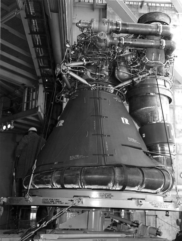
F-1 rocket engine G4049 engine vertical installer with S-IC-T
Click image for a 1137×1498 pixel version of this image in a new window. Photo courtesy Vince Wheelock. Cleanup by heroicrelics.
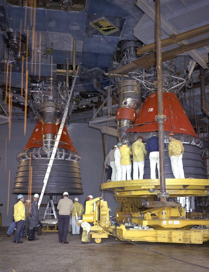
F-1 rocket engine G4049 engine vertical installer with S-IC-T
Click image to open its page at archive.org’s NASA Image collection in a new window.
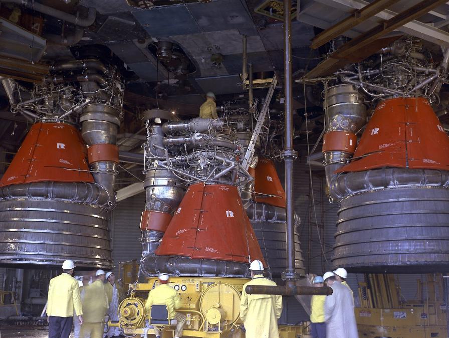
F-1 rocket engine G4049 engine vertical installer with S-IC-T
Click image to open its page at archive.org’s NASA Image collection in a new window.
Vince Wheelock, a Rocketdyne veteran, recalls there being six engine vertical installers in the Saturn V program. He didn’t elaborate, but it would seem that there was at least two at Marshall (one on the S-IC Test stand and one one the F-1 Test Stand) and at least one each at Kennedy Space Center and the Mississippi Test Facility (which has been renamed to the Stennis Space Center). I further speculate that there may have been one at the Air Force Research Laboratory at Edwards Air Force Base. The F-1 Rocket Engine Technical Manual: Engine Data describes how the vertical engine installer was used to install nozzle extensions when an S-IC stage was installed in the test stand at the Mississippi Test Facility (MTF):
The nozzle extensions, slave hardware, and MTF static test instrumentation are installed on the engines after the stage is installed in the test stand and after receiving inspection. Using Engine Handler Sling G4052 and overhead cranes, the nozzle extension is removed from the barge and from Nozzle Extension Handling Fixture G4080 and Handling Adapter G4081 and placed on Engine Vertical Installer G4049 on the lower stand work platform. The installer, with nozzle extension, is positioned below the engine; then the nozzle extension is installed on the engine, and the installer lowered.
This diagram illustrates an F-1 engine, in an Engine Rotating Sling G4050, being rotated from horizontal to vertical position, being placed on the G4049 Engine Vertical Installer, and raised into position. The last panel of the diagram shows the nozzle extension being installed.
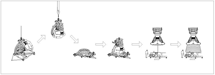
F-1 rocket engine G4049 engine vertical installer
Click image for a 2074×722 pixel version of this image in a new window. From page 50 (p. 51 in the PDF) of the “Data Pages” of the Marshall Space Flight Center F-1 Engine Static Test Stand entry on the Historic American Building Survey/Historic American Engineering Record. Extraction from an advance review copy and cleanup by heroicrelics.
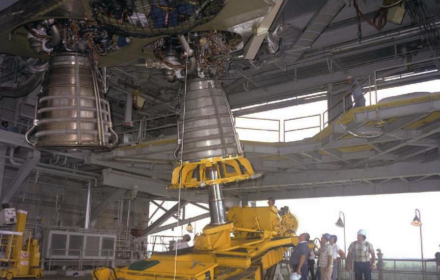
For a more detailed description of how an F-1 engine was installed in the F-1 Engine Test Stand at Marshall Space Flight Center, see my F-1 Test Stand Load and Test page. Here are two photos of the KSC installer. Note this installer rides on air bearings, rather than casters, for more precise movement and more clearance.
F-1 rocket engine G4049 engine vertical installer
Click image for a 2516×1960 pixel version of this image in a new window. Photo courtesy Vince Wheelock. Cleanup by heroicrelics.
F-1 rocket engine G4049 engine vertical installer
Click image for a 2821×2193 pixel version of this image in a new window. Photo courtesy Vince Wheelock. Cleanup by heroicrelics.
Advertisement:

More Than Seals & Cylinders……………..Solutions!
For additional technical specifications of the installer during the F-1 era, see my G4049 Engine Vertical Installer data sheet. Vince tells me that, after the Apollo program, the installers were all modified for use with the space shuttle main engine (SSME) program. Here are two photos showing a converted installer being used to install a in the shuttle Main Propulsion Test Article at the National Space Technology Laboratories (formerly the Mississippi Test Facility [MTF] and today the Stennis Space Center).
F-1 rocket engine G4049 engine vertical installer converted for Space Shuttle Main Engine (SSME) use
Click image for a 1706×1087 pixel version of this image in a new window. From page 7 of Main Propulsion Test Article (MPTA). Extraction and reconstruction by heroicrelics.
F-1 rocket engine G4049 engine vertical installer converted for Space Shuttle Main Engine (SSME) use
Click image for a 1526×1932 pixel version of this image in a new window. Scan courtesy Marshall Space Flight Center. Cleanup by heroicrelics.
A former Stennis employee contacted me via the Website. He tells me that he spent a “good number of the years” on test stand A-2 working SSME test. He was unaware that the engine installers were reused from the F-1 timeframe. He says that the one on A-2 sits on a movable platform and tilts up to be able to match the angle of the stand. It has the extension probe that fits into the throat of an SSME to support the powerhead with the engine at a cant. The one that was on test stand A-1 didn’t have the extension probe since the engine was installed vertical and thus the weight was evenly loaded on the nozzle. At least one of them had the smaller diameter nozzle platform that was used with the low-ratio nozzles that were used on SSME in early testing. It’s interesting that he mentioned low-ratio nozzles, because I didn’t think that the SSMEs, at least in the color photo above, looked quite right — the nozzle looked too “skinny”. But the installers’ work still isn’t done: The installers at Stennis are now being used in support of the J-2X program. I emailed William D. Greene, the NASA engineer who writes the J-2X Blog, after finding his J-2X Progress: Road Trip, Baby! post which mentiones the installers. He, too, was unaware of the engine installers’ heritage. Greene was kind enough to send the following two photos showing the installers used to install J-2X engine 10001:
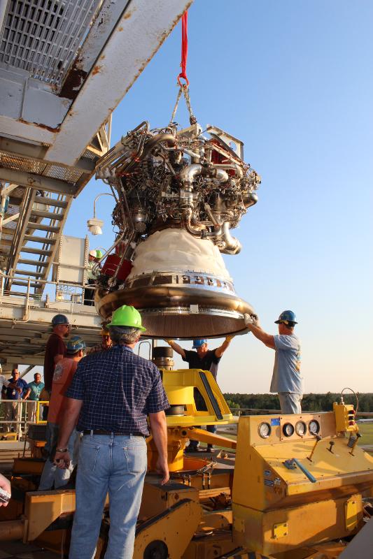
F-1 rocket engine G4049 engine vertical installer now being used in the J-2X program
Click image for a 3456×5184 pixel version of this image in a new window. Photo courtesy William D. Greene, Stennis Space Center.
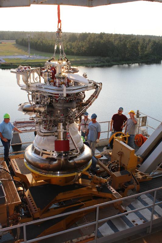
F-1 rocket engine G4049 engine vertical installer now being used in the J-2X program
Click image for a 3456×5184 pixel version of this image in a new window. Photo courtesy William D. Greene, Stennis Space Center.
Another post on the J-2X blog also has some photos of an installer in use. The former Stennis employee I mentioned above saw this blog post and pointed out that the table on the installer is a different color than the rest of the installer and speculates that they may have built a new table to match the J-2X geometry. NASA in general and Stennis in particular have a number of additional photos showing the engine vertical installers being used in the J-2X program: Advertisement:
Call Us Today!
F-1 Rocket Engine G4049 Engine Vertical Installer Telescopic Rocket Booster Installation Cylinder @ Seal & Cylinder Source, Inc.


