A Counterbalance Valve’s Biggest Enemy: Hysteresis
Most counterbalance valves have one to three dynamic seals in them, which introduce friction, resulting in hysteresis. When a cylinder is supporting a vertically  mounted load, and its directional valve shifts to lower the load, the load may fall uncontrollably as its weight pushes fluid out of the cylinder. To prevent this, a counterbalance valve, sometimes called an over-center valve, typically is installed downstream of the actuator. A counterbalance valve’s function is to maintain a set pressure against the load to keep it from over-running. For very low flow, a counterbalance valve can also serve as a thermal relief valve.
The counterbalance valve uses a pilot signal, usually from the inlet of the cylinder, to assist in opening a poppet. A pilot assist makes the counterbalance more efficient and reduces the power requirement and heat generation within the system.
More Than Seal & Cylinders………Solutions!
Counterbalance valve designs
The majority of the counterbalance valves are based on the same design principle as the differential area relief valve. Differential area relief valves must have 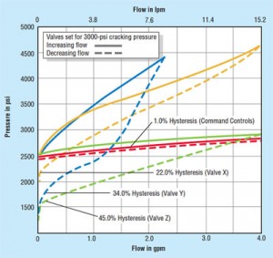 seals to prevent leakage. Most counterbalance valves have one to three dynamic seals in them, which introduce friction, resulting in hysteresis. Friction caused by the dynamic seals makes the valve stick, causing an overshoot in pressure. The counterbalance valve then shifts to correct itself and undershoots.
The result of hysteresis is bounce, loud chatter, or high-pitch squealing. Sometimes this chatter is caused by the design of the cylinder, not the counterbalance valve. The more dynamic seals in the counterbalance valve, the greater the hysteresis will be. When caused by the cylinder, no counterbalance valve in the world can reduce this chatter.
Treat symptoms or the cause
Many counterbalance valves offer options to treat the symptoms. Most counterbalance valves come with a pilot ratio anywhere from 1.75:1 to 12.0:1. Matching this selective pilot ratio to particular equipment sometimes corrects the problem. Another attempt to stabilize this situation is to have a short- or adjustable-stroke valve to restrict the flow until it becomes stable. However, doing so increases energy consumption. A small orifice or an accumulator can be installed in the pilot line to damp the valve’s response, thereby quieting its operation. But this technique is quite sensitive to fluid viscosity, and the valve becomes sluggish in cold temperatures. All these quick fixes treat the symptoms, but are not cures.
Advances in counterbalance valve technology are making controls easier and smoother. To reduce hysteresis in the counterbalance valve, all dynamic seals must be eliminated. Command Controls’ counterbalance valves have no dynamic seals, so they are virtually free of hysteresis. The valves are fast enough to follow any signal supplied to them, thus eliminating bounce, loud chatter, and high-pitch squealing. Their design has a high flow rating, which conserves energy, but remains controllable at very low flow. The valves also can serve as a full flow relief valve.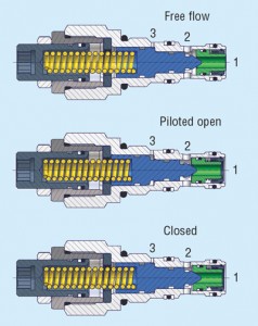
Away with dynamic seals
Because the pilot piston has no seals, a small amount of hydraulic fluid leaks past the pilot piston to purge the air from the pilot lines and provide warm oil to be circulated, making the valve very responsive. A small amount of leakage around the pilot piston has nothing to do with load-holding capability at the cylinder port. The best position for the valve to be mounted on the cylinder is with the valve’s adjusting screw pointing down, which allows fast air purging from the pilot line and the spring chamber. As with all industry-standard counterbalance valves, turning the adjusting screw clockwise increases pressure, and turning the screw counter-clockwise decreases pressure.
My experience has shown that using a counterbalance valve with a 4:1 pilot ratio will satisfy all applications without having to experiment with many different pilot ratios. Command Controls’ counterbalance valves are supplied with a built-in check valve for free reverse flow from port 2 to port 1. Other options include a sealed pilot piston for master/slave cylinder applications and a vented spring chamber to atmosphere (which makes port 2 insensitive to backpressure) for servovalve or regenerative circuits.