Don’t Take a Guess! Accelerate Prototyping and Validation of Hydraulic Systems Using Numerical Simulation
Power on, fingers crossed, and hope for the best… The practices of guessing and “we will see how it works” have no place in modern design. Competition pressure in the drive market, time, and cost limitations force fluid power engineers to abandon “good old” trial-and-error methods and replace them with more efficient simulation-based fast prototyping.
Simulation in Fluid Power
A typical hydraulic circuit consists of a large number of interacting components: transmission lines, pumps, accumulators, motors, cylinders, flow and pressure control valves, along with other related equipment. Each of these elements is characterized by individual static and dynamic properties, defined by mechanical design, actuation method, mechanical response, fluid properties, and other factors. It is relatively simple to predict the response of a single component, for example a proportional valve or pump swash plate, especially when the manufacturer provides sufficient data in the product data sheet. However, in many cases, it may be difficult to predict the dynamic response of the overall system along with interactions between dynamic subsystems. The challenge arises from the inherent nonlinear behavior of fluid power systems, resulting from the distinctive physical properties of oil compressibility and the square-root resistor law governing flow across a valve’s spool-throttling orifices. In the past, predicting the performance of a hydraulic drive was limited to static calculations and highly simplified linearized dynamic models based on differential calculus. The last two decades have brought tremendous progress in numerical computation and simulation technologies. Today powerful simulation tools are available to design engineers, making advanced analysis of hydraulic systems’ behavior and performance readily accessible.
Advertisement:

Call Us Today!
Due to high system complexity, performing a computer simulation can be a handy tool when working on a new system concept or troubleshooting an existing problem. Using a virtual model in an appropriate simulation program offers a completely new insight to the system’s properties, allowing validation and optimization of the design.
System modeling and simulation is often performed for any number of reasons. Some of the common ones are
- feasibility study and reality check for new designs;
- verification and optimization of the component selection and system concepts;
- prediction and analysis of system dynamic behavior, including hydraulics, mechanics, process (metal forming, injection molding, etc.) and closed-loop control algorithms (motion control, force control, etc.);
- analysis of machine productivity (achievable cycle rates), dynamic performance of the closed-loop control, accuracy, energy efficiency; and
- safety analysis under worse-case scenarios.
Simulation is one of the easiest ways to evaluate dynamic and nonlinear characteristics of electro-hydraulic drives, and is an efficient and inexpensive way to validate new ideas and concepts without the need for testing physical prototypes. This helps to reduce the risk of expensive field redesign and retrofitting of systems that do not meet required performance and/or stability criteria. The end result is that advanced simulation-aided prototyping drastically shortens application development time.
How Do You Approach Simulation of a Hydraulic System?
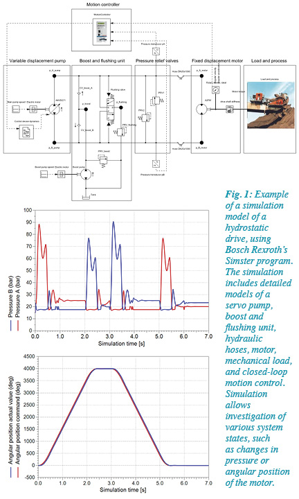
Depending on the goal of the simulation, an engineer can select from a number of commercially available simulation tools dedicated to hydraulic systems. Some examples of available products are Mathworks Simscape, ITI SimulationX, AMESim, and Easy5. Each program offers different component libraries, levels of the detail, and flexibility in the model’s parameterization. Bosch Rexroth has developed a range of tools for in-house use (MOSIHS, Simster, and HYVOS) that are tailored to the requirements of application support and development.
Before starting a simulation, the objectives of simulation study need to be precisely specified. What are the main goals of the simulation? What questions need to be answered by simulation? One example is investigation of the response of a closed-loop control under specified load scenarios. Other examples would be to compare energy consumption of two different system variants or presenting the functionality of a new hydraulic schematic. One pitfall is when application engineers specify simulation requirements too broadly. An example would be a request form stating, “The system should be simulated.” This would be too broad and general. Clear objectives help focus the simulation effort on efficient problem solving.
When planning or performing a simulation, it should be noted that a basic rule, which applies to every calculation, is “garbage in = garbage out.” This results in a simulation being as meaningful and accurate as the data that was provided. Experience shows that one of the most difficult problems in the overall simulation process is obtaining meaningful information about the mechanical loads (reaction forces due to forming process, gravitational and friction forces, etc). One critical fact concerns the mechanical inertia of the load to be actuated by hydraulic drive. The mechanical loads and inertias are critical when simulating dynamics and the closed-loop control since they determine the response of the system and performance of the closed-loop controls. An example is simulating positioning accuracy of a cylinder drive, but it makes little sense if the opposing process and frictional forces are unknown. Most model parameters can be obtained from the design documentation, CAD drawings (mechanical inertias), or—if simulating an existing application—“system identification” based on measured values (pressure, position, velocity, etc.). Unfortunately, in many cases, the engineer performing the simulation has to rely on experience and engineering “know-how.” The simulation input data should always be critically reviewed by a system designer and the application engineer.
Co-simulation of Complex Mechanical and Hydraulic Systems
In simple simulations, actuated mechanical systems can be modeled as “lumped” elements, which are simple single elements that represent a more complex set of elements. Often simple spring mass dampers are used in a hydraulic simulation to predict a system’s overall dynamic performance. This only works when a known mechanical resonance is known, dominant, and well defined. More complex mechanical systems, such as multi degree-of-freedom manipulators, toggle drives, moving platforms, and other systems, have multiple resonant modes within the mechanical system and are best modeled using multi-body dynamic simulation software (MBS). MBS models of complex mechanical systems can take into account the mechanical inertias and flexibilities of the various modeled elements. The MBS model can provide the torque or force inputs from elements, such as hydraulic cylinders, to drive the mechanical system and see the resulting reaction. Combining a simulation of an electro-hydraulic system and an MBS model allows analysis of the overall motion system performance, including interactions between the dynamics of a hydraulic drive, the closed-loop control, and resonances of the actuated mechanical structure.
An example of such an MBS-hydraulics co-simulation is a study by Bosch Rexroth of a blast furnace hydraulic distributor designed and built by Woodings Industrial in Mars, Pa.
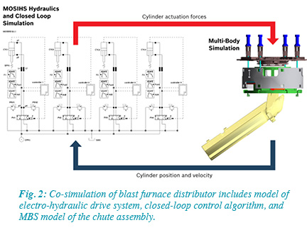
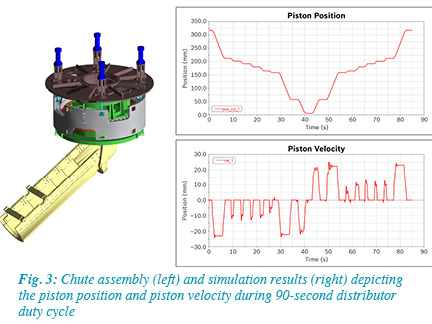
A hydraulic distributor, as seen in Figs. 2 and 3, provides two functions: rotation and tilting a chute to deposit layers of iron ore and coke into a blast furnace. The precision of the deposition of the materials is critical in controlling the melting process. The blast furnace can operate with increased efficiency based on the precision of the layers of the deposited materials charged into the furnace. The hydraulic and control systems have to react quickly to load changes and other disturbances in order to maintain high position accuracy of the chute. Additionally, a tight position tolerance between four differential cylinders must be maintained. A major challenge was a low natural frequency of hydraulic cylinder drive due to high mechanical inertia of the chute and long hydraulic lines between control valves and cylinders. The hydraulic system acts like a mass damper spring with a relatively low stiffness and damping, making accurate motion control difficult. To verify the targeted accuracy and repeatability of the Rexroth hydraulic drive system could be met, a complex multi-domain simulation was performed. The distributor chute hydraulic circuit and controls designed by Rexroth were simulated using “MOSIHS”, a proprietary simulation program for hydraulic and mechanical systems and controls. All relevant 3D CAD models of the Woodings-sourced components, such as the chute and the rotating distributor head mechanical systems, were imported into a commercially available MBS program that is coupled to the MOSIHS simulation tool. The co-simulation helped to optimize the hydraulic circuit design and component selection and the closed-loop controls. The simulation resulted in the need for a specialized control algorithm using load feedback information to effectively dampen the system oscillations and provide optimal performance. The simulation also allowed the design engineers to analyze and develop a better understanding of how the load forces act on the chute and how they could affect end-point accuracy.
Simulation Do’s & Don’ts
1. Keep the model as simple as possible, as complex as necessary.
Focus on the simulation’s targets, and focus on critical system components and subsystems that need to be included in the model. Often there is no need to simulate each individual valve or orifice in the system. Appropriately simplified and reduced models are easier to analyze and evaluate. Furthermore, simplifying the simulation can reduce the risk of input data errors and can shorten overall simulation times.
2. Test your simulation model.
Divide the model into small subsystems (actuators, power units, control blocks, etc.). Test each of the subsystems separately as you build the overall system model. This allows validation of the model in a step-by-step manner, similar to a real-world start-up. Steps such as verifying the sub-model of the power unit (checking pump flows, pressures, and setting the pump control) can be done first, followed by control valves and hydraulic actuators. In each step, valve flows, pressure drops, and pressure spikes in the hydraulic lines can be reviewed, as well as cylinder motions and other related functions can be noted.
3. Do not underestimate the influence of hydraulic lines on system dynamics. Consider the distance between the power unit, control manifolds, and actuators. The simulation should include the dimensions of hoses and lines, as well as the dynamic characteristics of those elements.
4. Check pressures in the system, and watch for high-pressure spikes, pressure drops, and possible cavitation in critical areas of the system.
5. Be skeptical and double-check results. Verify component catalog data, and review the operational conditions and compare them to the nominal published data. Check if simulated values are within the component specification with regard to allowable pressure, maximum permissible valve flow, and valve power limitations.
6. Calculate static process values, such as forces, flows, static pressures, etc., prior to simulation. These calculated values can be used to evaluate the validity of the simulation results.
7. Know the basic mathematics behind the component models(dynamics of a valve, pressure-dependant bulk modulus of hydraulic fluid) and understand the settings of the numerical solver and the influence on the simulation results.
Conclusions
The ability to accurately simulate hydraulic drives can increase the success of many complex applications. Validating design concepts, and investigating worst-case conditions and modes of operation can reduce operational and financial risks. Being able to verify performance criteria during the proposal and design stages can result in higher performing and more competitive designs.
By Jan Komsta and Paul Stavrou, Bosch Rexroth Corp.
Jan Komsta, Ph.D., is manager of new technologies, and Paul Stavrou is technology manager for Bosch Rexroth.
Advertisement:
More Than Seal & Cylinders………Solutions!