Motors, Hydraulic – Description
The function of hydraulic motors is to convert hydraulic pressure and flow into rotational mechanical energy via an output shaft. Motors are used where a rotational output is required and actuators are used where linear output is required. However, in operation motors are more similar to pumps than actuators and, in fact; the equations for motors are identical to the equations for pumps.
The output of a motor is a torque and an angular velocity (note: power = torque x angular velocity). Motors operate exactly opposite of pumps and, in fact, some motors/pumps take on dual roles (will operate as a pump or a motor depending on the position of controlling valves) in a hydraulic system. Like pumps, the governing equation for an ideal motor is
 (1)
(1)
where Q is the flow rate, Δp is the pressure drop across the motor, T is the output motor torque and ωis the motor angular velocity.
The main parameter of interest for hydraulic motors is the displacement (similar to pumps). Displacement is the amount of fluid that is displaced (flows through) the motor for each revolution of the shaft, and relates motor torque to the Δp across motor.
 (2)
(2)
In equation (2), D is the displacement in units of in3/rev (or similar) and Δp = p1 – p2, where p1 is the inlet pressure and p2 is the output pressure. The steady state performance of a pump is completely defined by equations (1) and (2).
There are 3 main types of hydraulic motors: piston, vane and gear.
A piston motor can be radial or axial. In a radial piston motor, the pistons are oriented radially from the shaft. An axial piston motor is similar to an axial piston pump and is the most common motor used in aerospace. A schematic of an axial piston motor is shown in Figure 1. As can be seen in the figure, the axial piston pump is identical to a piston pump, except that the swashplate angle is now fixed (i.e., there is no compensator and control piston). The inlet side of the motor is the high pressure side and the outlet is low pressure. The pressure difference causes the pump to rotate. Since the swashplate is fixed, speed of this motor is controlled by either controlling inlet pressure (Δp across the motor) or the flow rate. Also, like pumps, hydraulic motors tend to have 9 pistons, or possibly 7 (more pistons increase displacement and hence increase output torque). Piston motors provide the best sealing for high input pressures and work best in high torque, low speed applications. They have the best sealing and will be the most efficient. An axial piston motor with a fixed swashplate is unidirectional (rotate in 1 direction only). To be bi-directional, the swashplate would need to be variable position. Lastly, piston motors will have a case drain line to allow piston leakage to flow to return.
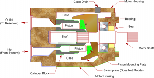
Figure 1 Axial Piston Hydraulic Motor
A vane motor is shown in Figure 2. Vane motors can be a good choice for a motor in high speed applications. The vane motor rotates as hydraulic fluid at high pressure flows through the motor to the outlet, or low pressure side of the pump. More vanes reduce output torque ripple, but also lead to higher pump friction. The vanes are attached to the drive shaft and fit closely to the housing ring (or cam ring) to minimize leakage. The vanes are pushed out by hydraulic pressure, centrifugal force or springs (springs are shown in Figure 2). For vanes which rely on centrifugal force to extend, the vanes are may be attached to the drive shaft (or rotor) via a slot, which allows the vanes to rotate in the slot and also move slide in the radial direction. As pressure is applied, the vanes will start to rotate the rotor (shaft). As speed is increased, the vanes move outward in the slots and contact the wall, providing a seal on the outer surface. The housing (or cam ring surface) can have a ramp shape to further reduce pressure at the pump outlet – this is possible because the rotor slot allows a vane to move radially and rotate to adjust to the housing (or cam ring) shape. For vane motors that utilize spring loaded vanes, the spring that helps to hold the vane against the housing (or cam ring) to ensure sealing at low Δp across the pump. This helps the motor develop starting torque faster. At higher speeds, centrifugal force helps hold the vanes out. The vane pump shown in Figure 2 has two ports, an inlet and outlet. It is possible to have a four port vane motor, which splits the flow through two separate paths. A four port vane motor will have twice the torque, but will operate at ½ the speed as a similar sized two port vane motor. Inlets for a four port motor will be at opposite ends of the motor to balance bearing loads. For vane motors, a valve can control which port has high pressure and which port has low pressure, leading to a bi-directional motor. Vane motors are not as efficient as piston motors but are better suited to high speed operation. Vane motors become less efficient at high inlet pressures (due to potential for more slippage and leakage past the vanes). Vane motors are also more inefficient at low speeds. Vane motors can be operated in a reversible (bi-directional) manner and will be less noisy then other pump types. They will generally be less expensive than piston motors.
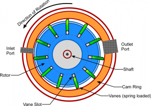
Figure 2 Vane Hydraulic Motor
A gear motor schematic is shown in Figure 3. This gear shows two spur gears rotating in a common housing. Both gears rotate, although only one gear is connected to the output shaft. Fluid enters where the gears mesh together as shown in Figure 3. The gears then rotate in the direction of the arrows, as the greatest pressure drop is around the outside of the housing (if the gears rotated the other direction then they would be pushing against system pressure). Also, by putting the input port where the gears mesh together puts the effective area of 2 gear teeth against the resisting pressure acting on 1 gear tooth. Gear motors work best in high speed applications. The efficiency of gear motor is lower at low speeds and increases (gets better) at high speeds.
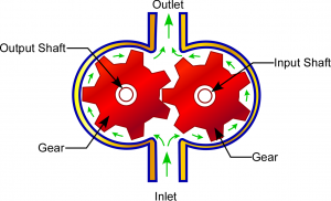
Figure 3 Gear Hydraulic Motor
Gear motors are generally very compact relative to their displacement and are able to operate at high speed. They are also less expensive than a piston or vane motor. However, they can be noisy and are the least efficient of the 3 motor types. Gear motors can be operated in a reversible (bi-directional) manner.
Pump performance varies with speed and load. A typical performance chart for a hydraulic piston motor is shown in Figure 4. As can be seen in the top chart, the volumetric efficiency is high and constant over the range of speeds. However, the overall efficiency (which is the product of the volumetric and mechanical efficiencies) drops off at higher speeds, which implies there is an optimal speed range for each particular hydraulic motor. The lower chart shows a linear relationship between flow and speed, where the slope of the line is the displacement. Also shown in the lower chart is the motor output torque, which tends to drop off at higher speeds.
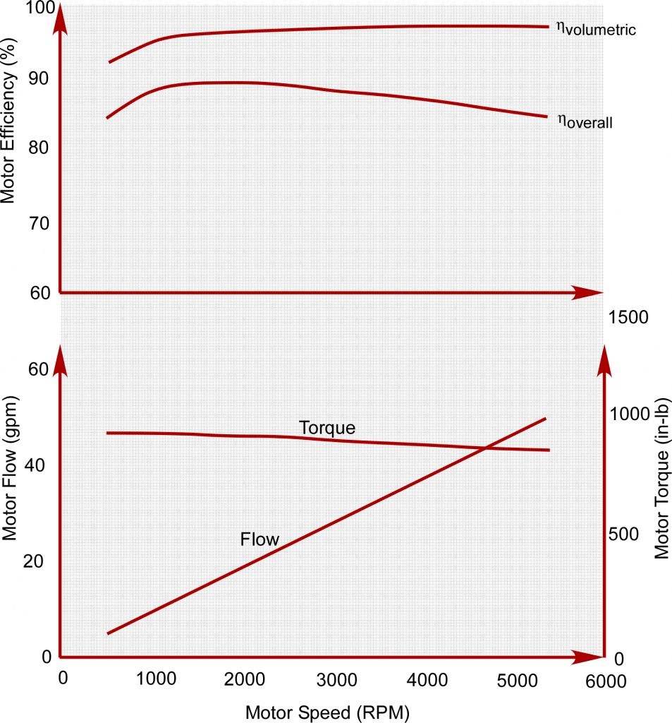
Figure 4 Typical Piston Hydraulic Motor Performance Graphs
As stated above, motors can be uni-directional or bi-directional, but in aerospace bi-directional motors are almost always used. An exception would be pump/motor units connected by a power transfer shaft, which tend to be a piston pump/motor (whether a pump or motor depends on direction of rotation) – see Figure 5. Most motors also tend to be fixed displacement, unlike a pump where the compensator changes the pump displacement based on pump outlet pressure. In motor design, one of the key elements to a good motor is minimizing internal leakage past piston and vane seals, under both low load and low speed operation. Leakage is the flow that passes through the motor without creating any work output. Another key element is the ability of the pressure/load bearing surface to withstand the applied loads – this is bigger issue with vane pumps.
The overall benefits of hydraulic motors include the ability to control to an infinite speed (as opposed to discrete increments), ability to withstand stall torque easily and relatively high power to weight ratios. Motors are self-contained units and simple in operation, which leads to high reliability. The main issues with hydraulic motors in service are excessive leakage, seal failures and noise.
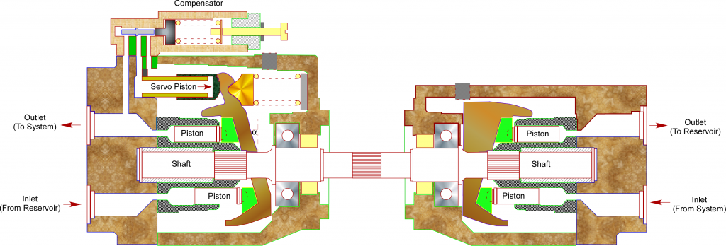
Figure 5 Piston Pump and Motor Unit (Uni-Directional)
Motor Design Considerations
The most important characteristics for hydraulic motor performance are listed below.
Motor Type –as described above there are 3 basic types of hydraulic motors (piston, vane and gear). Each type has advantages and disadvantages and the specifications will vary between the 3 motor types.
Displacement –fluid volume displaced (flows through the motor) per revolution of the output shaft
Operating Torque– output torque of the motor, usually given at the rated speed and rated flow for a given inlet pressure. A plot of output torque may also be available. Note this is related to operating power through motor speed.
Operating Power– output power of the motor, usually given at the rated speed and rated flow for a given inlet pressure. A plot of output power may also be available. Note this is related to operating torque through motor speed.
Operating Pressure–expected inlet pressure of the motor during normal operation, which must be compatible with the design operating pressure for the system and the expected pressure drop between the pump and the motor. This pressure will be less than the pump outlet pressure.
Maximum Operating Pressure – maximum allowable inlet pressure to the motor. This should normally be equal to system pressure or higher.
Operating Speed– this is the speed of the motor at the operating pressure.
Operating Flow– flow rate through the pump at the nominal operating pressure and operating torque
Maximum Flow –maximum flow rate that is possible through the motor. Maximum flow will occur at the maximum motor inlet pressure under no load conditions.
Maximum Allowable Viscosity – motor manufacturers provide recommended ranges of fluid viscosity. Motor operating parameters provided by the manufacturer will be valid within the recommended range of viscosity. At high viscosity levels, motor capability will start to decline.
Maximum Operating Temperature – highest temperature the motor is expected to see in service. This temperature is used to ensure motor materials and seals are compatible with the operating environment of the motor.
Motor Efficiency– higher efficiencies are preferred. Efficiency is the difference between power in and power out. The difference is caused by frictional losses and seal leakage.
Motor Installation Considerations
The most important parameters for the installation of hydraulic motors are listed below.
Dimensions –overall dimensions for the motor is required to determine the installation volume required
Interfaces –interfaces include tubing/hose connections and locations on the motor, as well as mounting lugs and output shaft location.
Weight –weight of the motor, which is usually provided as a dry weight. When filled with fluid, weight will be higher.
Noise –Motors run at high speed and create noise. A specification for maximum noise level should be considered for motor installations.
Attachments –method of attachment of the motor to the airframe affects structural rigidity of the motor and also noise (vibration) transmission into the airframe. Motors can have high starting torque causing large loads to be reacted through the attachments on start up. Continuous operational torques will affect the fatigue and durability of the attachments.
Motor/Shaft Alignment – Alignment of motor to shaft needs to held to tight tolerances. Considerations are tolerance stickups, relative motion between motor and shaft, possible angular displacements on installations, spline teeth dimensions, etc. Improper alignment can cause excessive vibration (leading to premature failure), or failure of the motor seals.
Splines –Beyond alignment, spline wear is an important consideration. Usually some lubrication (grease) is applied to the splines to minimize wear. Selection of lubrication should include temperature, corrosion inhibiting and reasonable life of the grease before breakdown occurs.
Torque Requirements– Both start-up torque and running torque should be considered. Start-up torque is higher than running torque. Start-up torque accelerates the mass/inertia of the motor and load, leading to temporary high stresses within the mounting hardware and motor. This is more of a concern on installations with high load inertias. Obviously, the speed of the motor must match the manufacturer’s recommended speed for actuation device (such as a ball screw actuator). A gear arrangement may be used, if required.
Axial and Radial Shaft Load Capability – Ensures motor shaft and splines are adequately sized for static and fatigue loads that the motor will see over it’s operating life.
Inlet/Outlet Line –Inlet and outlet lines/fittings must be matched to the motor
Direction of Rotation – Motors can be uni-directional or bi-directional. Aerospace applications tend to be bi-directional pumps. Obviously, the control valve position must be matched to the appropriate direction of rotation.
Speed Control of Hydraulic Motors
Usually, the goal of a hydraulic motor is to produce a constant rotational speed at a sufficient torque to move the load. The two methods to control speed are use of a hydraulic pump (either fixed delivery or variable delivery, but usually variable delivery) or through a valve. Valve control may be through a flow control valve, pressure regulating valve or a servovalve. As discussed in the mathematical equation section for motors (see Motor, Hydraulic –Equations), rotational speed of the motor will vary with load and flow varies with speed. Also, torque is a function of Δp across the motor.
Consider a fixed delivery pump. A fixed delivery pump will produce a constant flow. Assuming a pressure relief valve does not open, a constant flow rate from the pump will flow through the motor but the inlet pressure will vary with load. Therefore, a fixed delivery pump will produce a constant speed but the torque will vary with load.
A variable delivery pump will vary flow to produce a constant pump outlet pressure. At the motor, this will maintain a constant motor inlet pressure, so that the Δp is constant across the pump and hence the torque is constant across the pump. Therefore, a variable delivery pump, in the absence of any valve control, will produce a constant torque but a speed that varies with load.
A flow control valve regulates flow rate to a constant value. This is accomplished by controlling the Δp across an orifice. Therefore, a flow control valve will result in a constant flow through the motor with a varying motor inlet pressure. In effect, use of flow control valve produces a constant motor speed with a torque that varies with load, similar to a fixed delivery pump. This assumes system pump flow and pressure to the valve are constant.
A pressure regulating valve regulates valve outlet pressure by controlling flow. This effect will produce a constant motor torque with a speed that varies with load, similar to a variable delivery pump. This assumes system pump flow and pressure to the valve are constant.
In the case of servovalve control, a digital control system will sense rate somewhere in the system (such as flap rate) and modulate the servovalve to maintain a desired rate. This is a speed control, feedback control system. Parameters within the control loop, such as valve constant and loop gain, are sized to give optimal performance at the design conditions. Ideally, the speed control loop is a linear control loop without nonlinearities. However, in practice, hydraulic systems are inherently nonlinear which may cause some stability and performance issues if the system is not designed properly. In particular, high stiction and start-up forces in the system may lead to jerky starts as the control loop attempts to find equilibrium (in terms of speed). Another factor in use of servovalves to control a motor is that 4 way spool valve will regulate both supply pressure and return pressure to the motor (so inlet and outlet port pressures will be affected by a servo valve). The pressures will vary according to the relations
where PS = P1 + P2 and Load Pressure = PL = P1 – P2.
For other types of control, the downstream pressure, P2, will be the return pressure.
Lastly, if hydraulic motor speed is too high – which is often the case – a gear box can be installed on the motor output shaft to reduce speed. For large gear reductions, a planetary gear train can be used.
Applications of Hydraulic Motors
The most common application of hydraulic motors in aerospace vehicles are operation of wing trailing edge flaps and leading edge slats. In these applications, a hydraulic motor drives the flap or slat via a torque tube that runs along the trailing edge or leading edge. Gearboxes (90 degree, bevel and offset gear arrangements) connect the torque tube along the trailing edge or leading edge. Typically a ballscrew actuator with a gearbox extends and retracts the flap or slat. There are usually at least 2 ballscrew actuators per flap or slat panel. Other applications for hydraulic motors are folding wing control, cargo doors and ramps and landing gear. Motors are usually high speed with low torque that are geared down to provide a lower speed and higher torque.