IRON PISTON RINGS
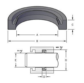
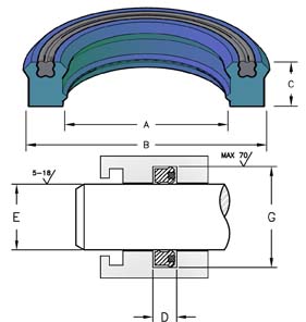
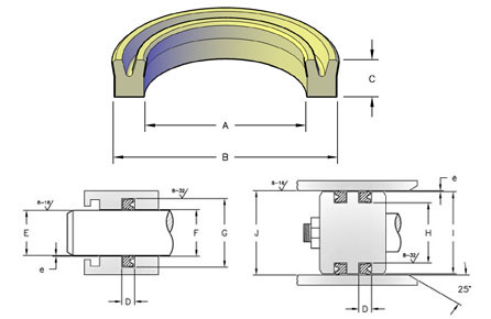
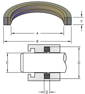
When using iron piston rings, it is crucial to use the correct groove design for proper performance of the cylinder. Please use the following guidelines when cutting an iron piston ring groove
- GROOVE WIDTH:
- To permit the ring to slide freely into the groove, the groove must be at least 0.001 in. wider than the maximum piston ring width with a tolerance of +0.003 in./-0.000 in.
- GROOVE DEPTH:
- Grooves must be at least 0.015 in. deeper than the maximum radial wall thickness of the piston ring with a tolerance of +0.003 in./-0.000 in. This is to avoid any possibility of the ring bottoming in the groove when the ring is compressed to its working diameter.
- RADIAL CLEARANCE:
- The radial clearance between the cylinder bore and piston should be less than 1/3 of the radial wall thickness of the piston ring to ensure sealing effectiveness.
| SEAL INFORMATION | |
|---|---|
| MATERIAL | IRON |
| PART NUMBER | (Prefix) – (OD) |
| BC = Butt Cut | |
| H = Hook Joint | |
END CLEARANCE
End clearance on piston rings depends on ring design, material and application. The following end clearances are provided as a standard for hydraulic cylinder applications.
| DIAMETER | BUTT & ANGLE CUT END CLEARANCE | OVERLAPPING JOINT & STEP CUT CLEARANCE |
|---|---|---|
| .500 – 4.561 | .003/.010 | .005/.015 |
| 4.562 – 19.97 | .005/.015 | .010/.020 |
| 19.971 – 30.5 | .010/.025 | .015/.030 |